The Hot Shot II system was designed with the Firefighter in mind. An emergency is not the time to perform complicated procedures in order to operate the foam system. The Hot Shot II system requires the operator to turn ONE SWITCH.
It’s that easy!
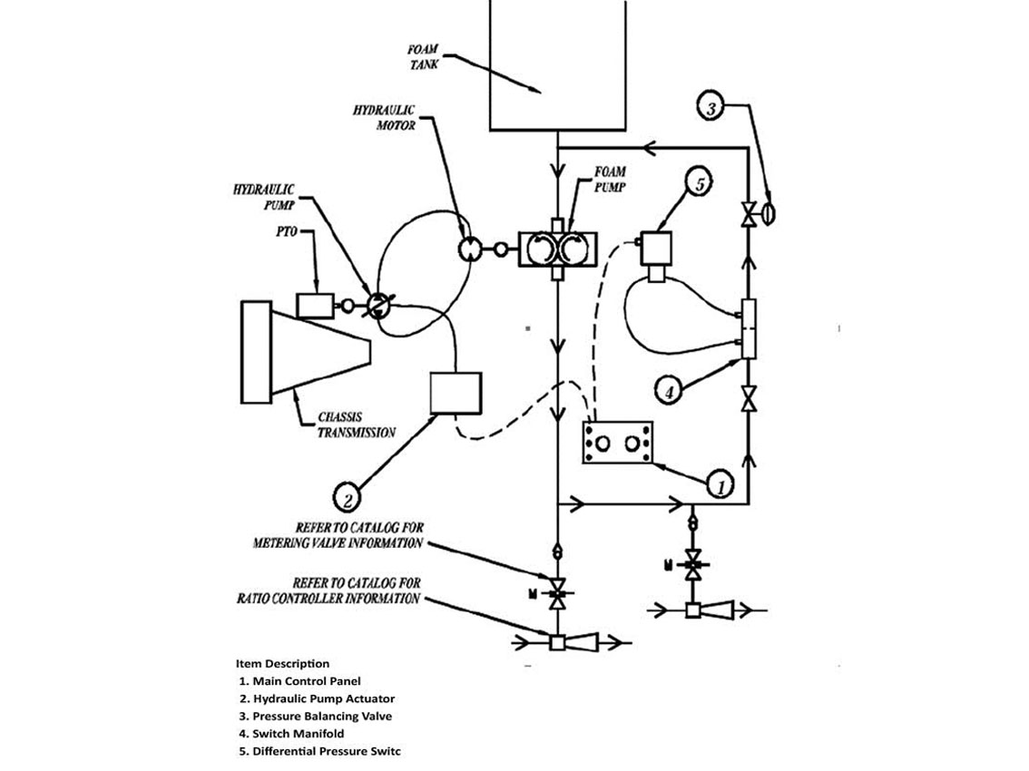
The WILLIAMS FIRE & HAZARD CONTROL Hot Shot II Foam System combines the proven performance and reliability of balanced pressure technology with the modern efficiency of a hydrostatic drive. This system was developed to handle the modern (Thixotropic) AR-AFFF type concentrates in use today. A small amount of concentrate is always being circulated through the foam manifold and returned to the suction side of the foam pump. This keeps the foam concentrates from becoming gelatinous and ensures that foam is immediately available should a discharge be opened. The hydrostatic drive system is powered from the chassis transmission via a Power Take Off (PTO). This allows the system to be engaged at any engine RPM, since there is no time to bring the engine to an idle when every second counts. It also allows the concentrate pump to operate independently from the water pump. This feature enables loading or unloading of foam concentrate independent of the water pump. The hydrostatic drive permits the system to operate over a broad operating range not possible with conventional Balanced Pressure technology.
System Overview
The Hot Shot II balanced pressure foam proportioning system is a hydraulically driven “demand” system utilizing a positive displacement foam pump and pressure control circuit that provides foam concentrate supply at a pressure balanced or matched to that of the fire water pump. The pressure control circuit and variable displacement hydraulic drive system regulate and adjust foam pump output, independent of engine/PTO speed, to maintain this proper pressure balance as foam concentrate “demand” increases or decreases to meet total foam solution discharge requirements. Based on specific installation chassis transmission, PTO drive ratio and hydraulic drive pump/motor sizing, maximum foam pump output may be achieved at or near engine idle speeds.
In operation, the pressure balanced foam supply is delivered through a metering valve to a modified venturi device known as a “ratio controller”’ (RC). Each foam capable discharge is equipped with its own ratio controller and matching metering valve. Water flow through the ratio controller creates a “metering pressure drop” within the device as a result of venturi effect. This pressure drop allows the pressure balanced foam concentrate supply to enter the discharge line proportionate to the specific water flow rate within the ratio controller’s design flow range. Each metering valve has seven distinct detent positions that provide for OFF and six standard proportioning rates of 1-6% in 1% increments.
The pressure control circuit is comprised of a “pressure control valve” (PCV), orifice flow tube and pressure differential switch. The PCV regulates foam pump discharge “by-pass” flow through the orifice flow tube where a pressure differential is developed and sensed by the pressure differential switch. This by-pass flow is returned to the suction side of the foam pump rather than the foam concentrate tank thus allowing proportioning of dissimilar foam concentrates without the risk of foam cell contamination. When by-pass flow drops below the design minimum, the pressure differential switch signals the control panel to increase hydraulic drive speed thereby increasing foam pump output. Conversely, when by-pass flow increases above the design maximum, the pressure differential switch signals the control panel to decrease hydraulic drive speed to decrease foam pump output. This decrease/increase in by-pass flow is determined by foam concentrate demand based on an increase/decrease in total solution flow as discharges are opened/closed and results in very precise and rapid automatic pressure balance adjustments. All foam pump output flows through the entire foam distribution piping/manifold system thus acting as a large heat exchanger and preventing foam concentrate overheating as a result of prolonged, no flow “deadhead” operation. During any deadhead operation, hydraulic drive speed is reduced to produce foam pump output between the minimum and maximum by-pass flow and therefore minimizing foam concentrate heating.
Ordering Information
Hot Shot II System Part Number
| Model | Base System | Single Tank Control | Dual Tank Control |
| Hot Shot II 60/12 VDC | 10332 | 12027 | 12035 |
| Hot Shot II 60/24 VDC | 10498 | 12028 | 12036 |
| Hot Shot II 150/12 VDC | 10426 | 12029 | 12037 |
| Hot Shot II 150/24 VDC | 10452 | 12030 | 12038 |
| Hot Shot II 150 FLP*/12 VDC | 17758 | 12029 | 12037 |
| Hot Shot II 150 FLP*/24 VDC | 17759 | 12030 | 12038 |
| Hot Shot II 250/12 VDC | 10427 | 12031 | 12039 |
| Hot Shot II 250/24 VDC | 10453 | 12032 | 12040 |
| Hot Shot II 300/12 VDC | 10428 | 12033 | 12041 |
| Hot Shot II 300/24 VDC | 10462 | 12034 | 12042 |
| Hot Shot II 300 FLP*/12 VDC | 17707 | 12033 | 12041 |
| Hot Shot II 300 FLP*/24 VDC | 17708 | 12034 | 12042 |
*Compatible with Fire Lion foam pumps.
Hot Shot II Ratio Controller Kits (including ratio controller, metering valve, & foam check valve)
| Ratio Controller Size | Part Number for Class B Foam | Part Number for Class A/B Foams |
| 2” | 11662 | 11672 |
| 2.5” | 11663 | 11673 |
| 3” | 11664 | 11674 |
| 4” | 11665 | 11675 |
| 5” | 11666 | 11676 |
| 6” | 11667 | 11677 |
| 6”, Hi Flow | 11668 | 11678 |
| 8” | 11669 | N/A |
| 8” – 1%/3% | 11670 | N/A |
| 8” – 3%/6% | 11671 | N/A |
Remote Foam Metering Controls for Hot Shot II Systems
| Controller Size | Part Number for 12 VDC | Part Number for 24 VDC |
| 2” and 2.5” | 12043 | 15777 |
| 3” and 4” | 12044 | 15778 |
| 5” and 6” | 12045 | 15779 |
Notes:
Complete Hot Shot II System consists of base system, choice of either single or dual tank controls, and required size(s)/quantity of ratio controller kits for Class B foam only or for both Classes A and B. Remote foam metering control is optional add-on for both Class B and Class A/B systems.